User Manual for Laserbox Basic Software (PC Version)
This page describes how to use the Laserbox basic software.
1. Obtain and install Laserbox basic
3. Connect xTool D1 to Laserbox basic
1. Obtain and install Laserbox basic
(2) Double-click the software you've downloaded to install it.
![]()
Click Yes when you are asked "Do you want to allow this app to make changes to your device?" and then continue the installation as prompted.
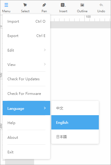
2. Select a language
3. Connect xTool D1 to Laserbox basic
Way 1: Through serial port
If you are to connect xTool D1 to Laserbox basic through a serial port, perform the following steps:
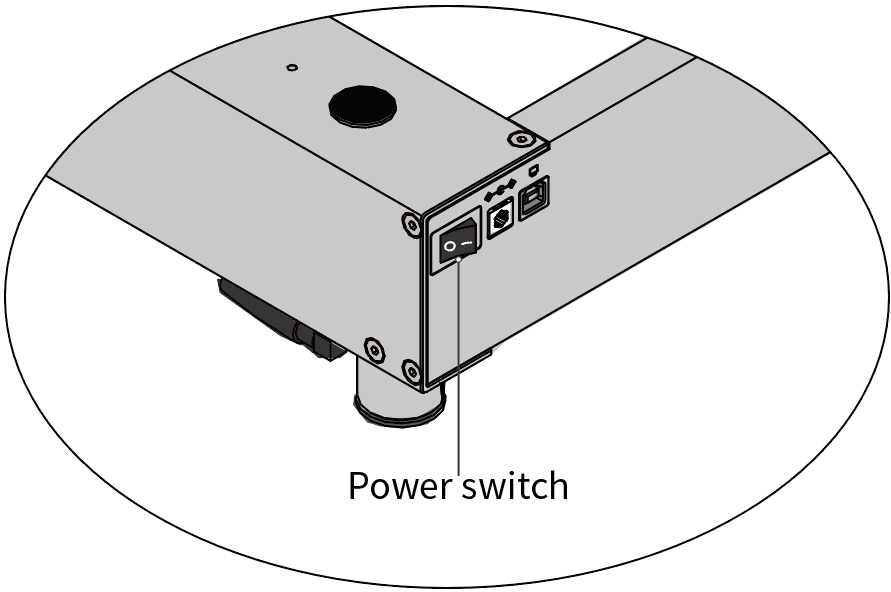
(1) Turn on the power switch of xTool D1.

(2) Double-click the Laserbox basic icon to open it.

(3) Use the USB cable to connect xTool D1 to your PC.
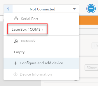
(4) Click + in the upper-right corner to add a device.
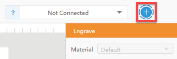
You can see your xTool D1 in the connection drop-down list box.

(5) Click your xTool D1.
Laserbox basic automatically connects to it.
Way 2: Through Wi-Fi
If you want to use xTool D1 wirelessly, you can set up the connection between xTool D1 and Laserbox basic through Wi-Fi. Perform the following steps:
(1) Turn on the power switch of xTool D1.
(2) Double-click the Laserbox basic icon to open it.

(3) Use the USB cable to connect xTool D1 to your PC.
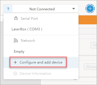
(4) Click + in the upper-right corner to add a device.

You can see your xTool D1 in the connection drop-down list box.
(5) Click + Configure and add device.
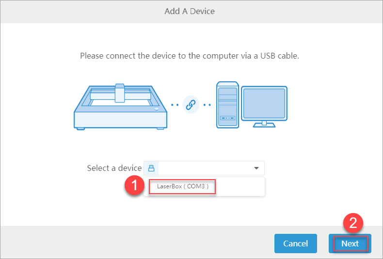
(6) Select your xTool D1 and click Next.
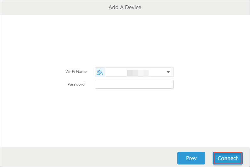
(7) Enter the Wi-Fi name and password, and then click Connect.
Note: Make sure that the Wi-Fi network you set is the same as the one used by your PC.
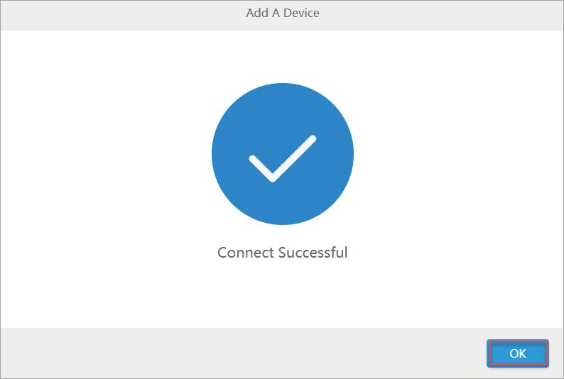
After the connection is complete, you can see a message indicating that the connection is successful. Click OK.
(8) Remove the USB cable that connects your xTool D1 to your PC.
Now, you can use your xTool D1 wirelessly.
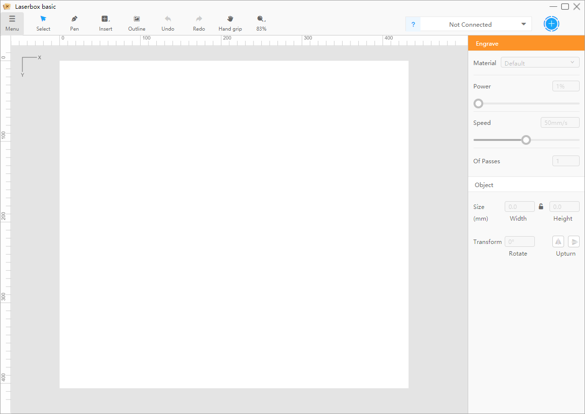
4. Get to know the UIs
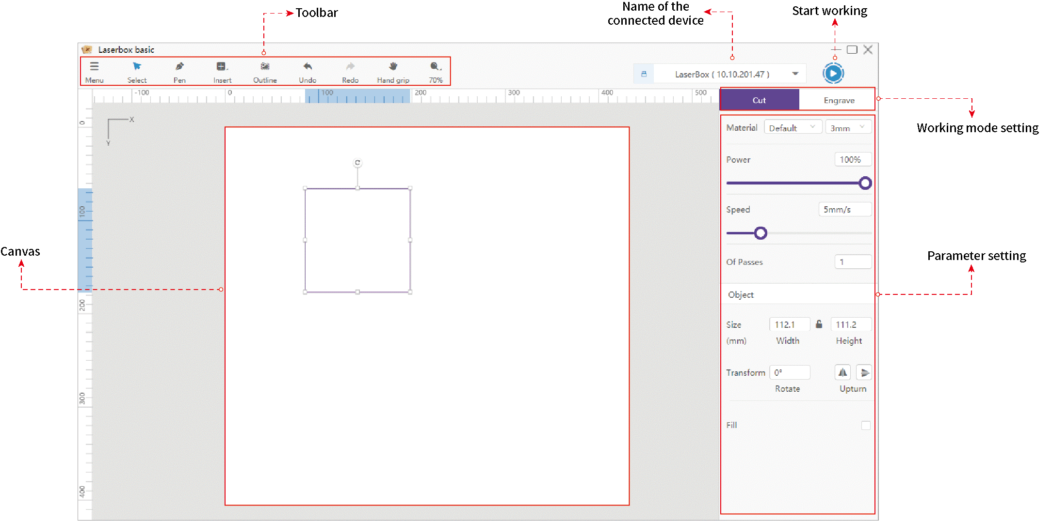
Toolbar
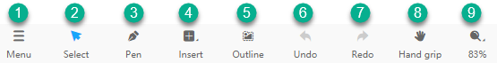
① Menu
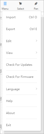
- Import: choose it to import a file, such as an image or project file
- Export: choose it to export all the content on the canvas as a project file
After exporting a project file, you can import it to Laserbox basic again to use it.
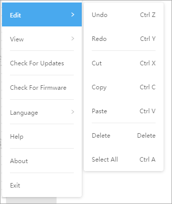
- Edit: choose it to redo or redo an action or edit the content on the canvas
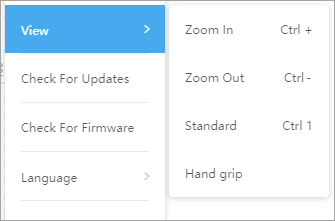
- View: choose it to zoom in or out on the canvas, to adapt the canvas for the window, or move the canvas.
- Check for Updates: choose it to check whether a new version of Laserbox basic is available
- Check for Firmware: choose it to check whether a new version of firmware is available for the device connected to Laserbox basic
- Language: choose it to set the UI language. Currently, the English and Chinese options are available.
- Help: choose it to go to our support websie
- About: choose it to view information about the Laserbox basic software
② Select
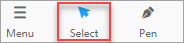
After you choose Select, you can click to select an item or drag the mouse pointer over the items to select them.
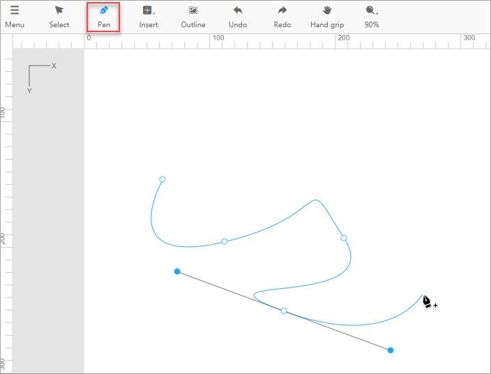
③ Pen
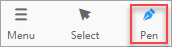
After you choose Pen, you can create vector paths on the canvas, just like what you can do in Adobe Photoshop and Illustrator.
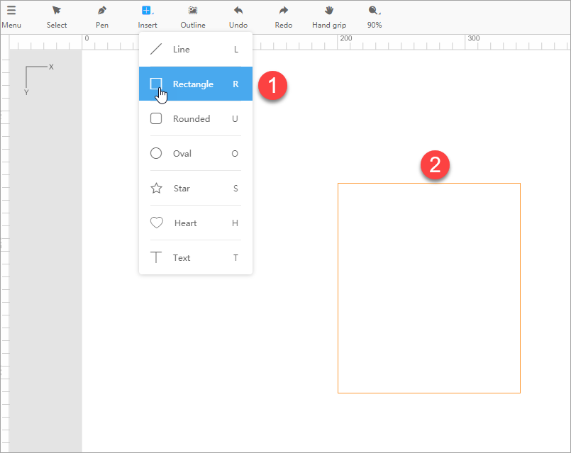
④ Insert

You can choose Insert to insert a shape, such as a line, rectangle, rounded rectangle, oval, star, heart. You can also choose to insert a text.
After inserting a shape, you can choose Select to select it and transform it.
⑤ Outline
You can click Outline to extract the outline of an image. For details, see "Extract the outline of an image."
⑥ Undo
When you choose Undo, the last action is canceled.
⑦ Redo
When you choose Redo, the last canceled action is performed again.
⑧ Hand grip
After you choose Hand grip, you can move the canvas by dragging the mouse.
⑨ Scaling
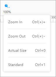
You can choose to zoom in or out on the canvas, restore the image to the actual size, or adapt the canvas for the window.
Canvas
On the canvas, you can:
Draw vector paths by choosing Pen
Drag your mouse to draw a shape after choosing Insert
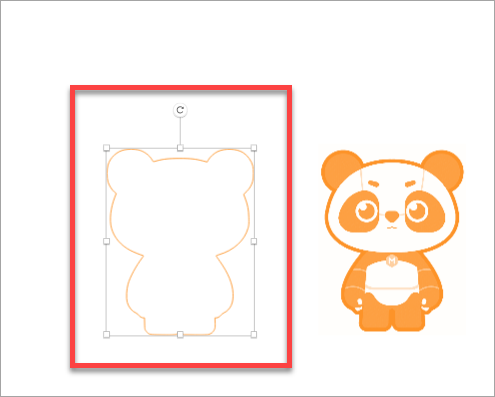
Extract the outline of an image
Import an image, select it, and choose Outline to extract the outline of the image.
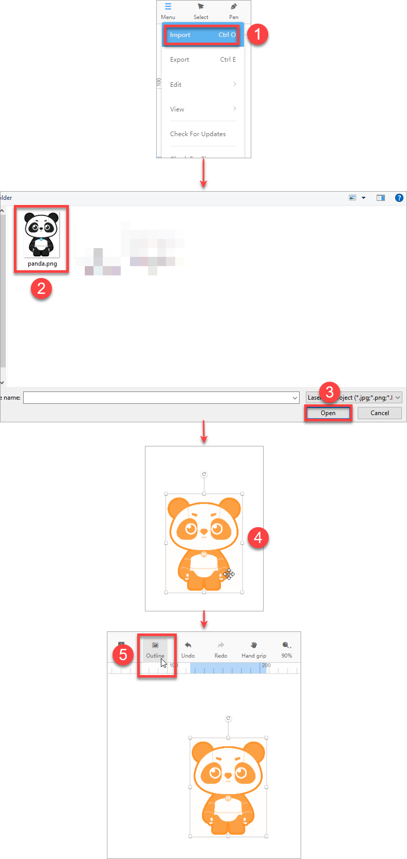
The outline is obtained, and you can use it for cutting.
Cutting/Engraving parameter settings
The cutting function of Laserbox basic is available only for vector paths, and the engraving function is available for both vector paths and images.
You can select an item to see whether the two functions are available.
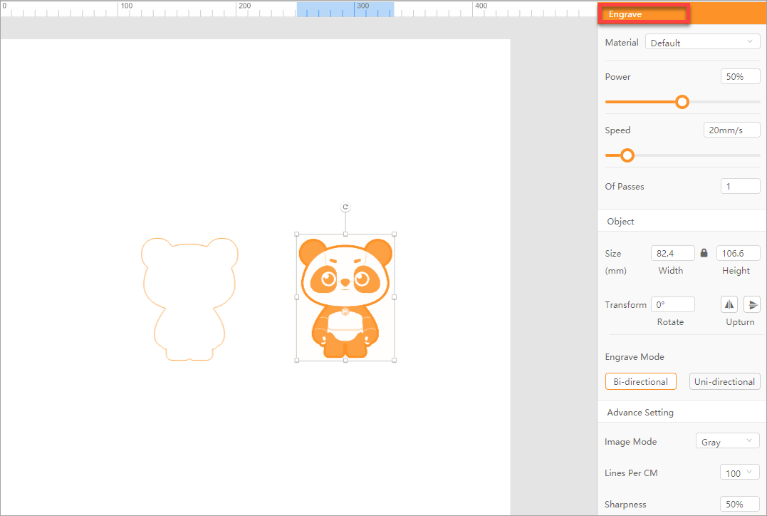
As shown in the following figures, the cutting and engraving functions are available for the selected item.
- When you choose the cutting function for it, the outline turns into purple, which indicates that you are to cut the shape from the material.
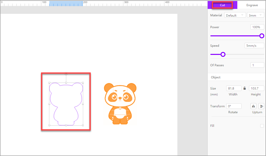
- When you choose the engraving function for it, the outline turns into orange, indicating that you are to engrave the path on the material.
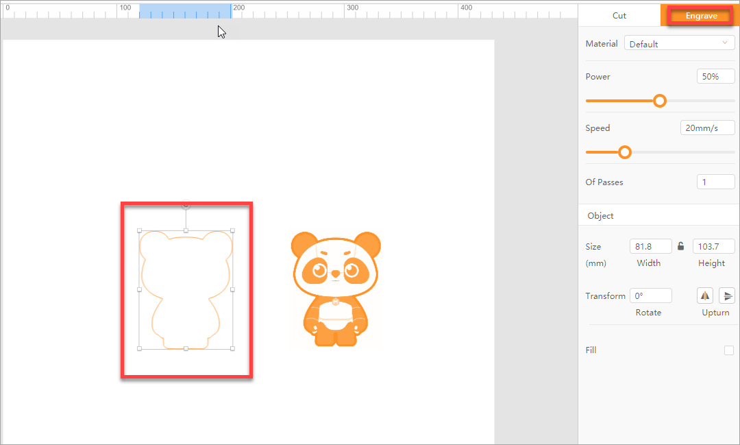
- As shown in the following figure, only the engraving function is available for the selected item.
Set parameters for cutting
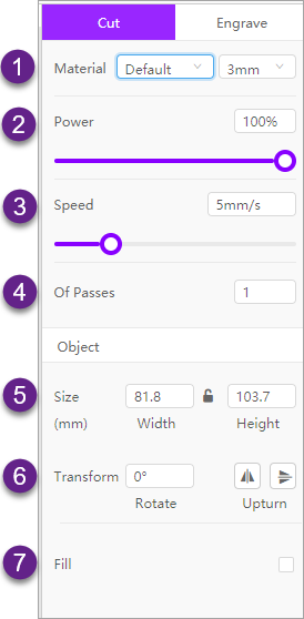
① Select the material you use and set its thickness
② Set the power for cutting
Setting range: 1-100 (%)
③ Set the speed at which cutting is to be performed
Setting range: 1-20 (mm/s)
④ Set the number of processing times
⑤ Set the size of the object to be cut
⑥ Transform the object
⑦ Fill a color in a closed path or text
Set parameters for engraving
Parameters for vector path engraving
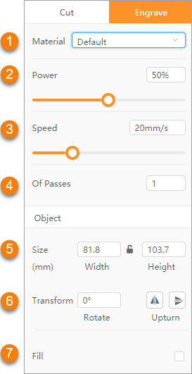
① Select the material you use
② Set the power for engraving
Setting range: 1-100 (%)
③ Set the speed at which engraving is to be performed
Setting range for vector paths: 1-80 (mm/s)
Setting range for bitmap images: 1–180 (mm/s)
④ Set the number of processing times
⑤ Set the size of the object to be engraved
⑥ Transform the object
⑦ Fill a color in a closed path or text
Additional parameters for image engraving
For image engraving, the following additional parameters are provided.
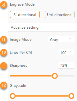
⑧ Set an engraving mode
- Bi-directional: The laser head performs two-way engraving.
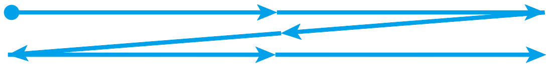
- Uni-directional: The laser head performs one-way engraving.
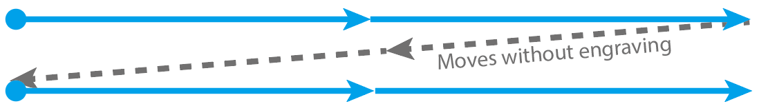
In most cases, it takes less time to engrave an image in the bi-directional way than in the uni-directional way.
⑨ Select an image mode
An image mode you select here is actually an image filter. For example, Bayer is a mosaic filter.
With the other settings unchanged, the output of an image on a wooden board varies according to image mode, as shown in the following figure. You can select a mode as required.
⑩ Set the number of lines in one centimeter
This parameter determines the resolution of the image to be engraved.
⑪ Set the sharpness of the image to be engraved
With other settings unchanged, sharpness determines the clarity of detail in an image.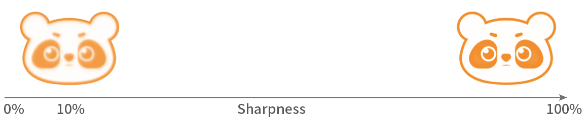
⑫ Set the grayscale of the image to be engraved
Grayscale indicates the black and white intensity, ranging from white to black.
Additional parameters for text engraving
For text engraving, the following additional parameters are provided.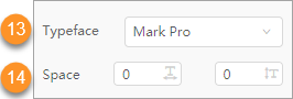
⑬ Set the typeface for the text to be engraved
Click to select a font.
⑭ Set the space for the text to be engraved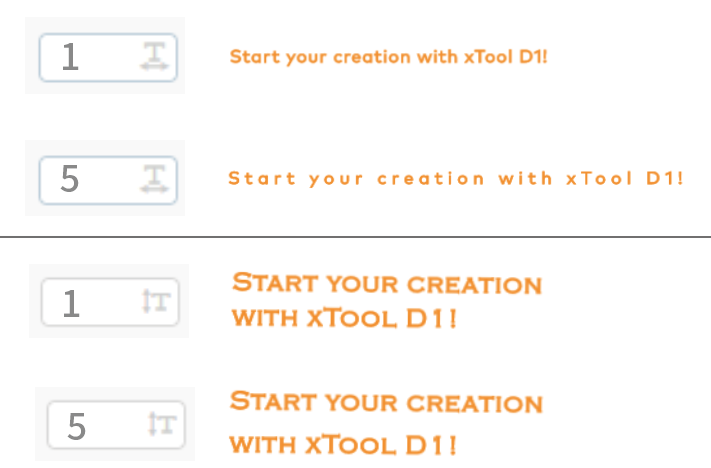
Laser positioning mode
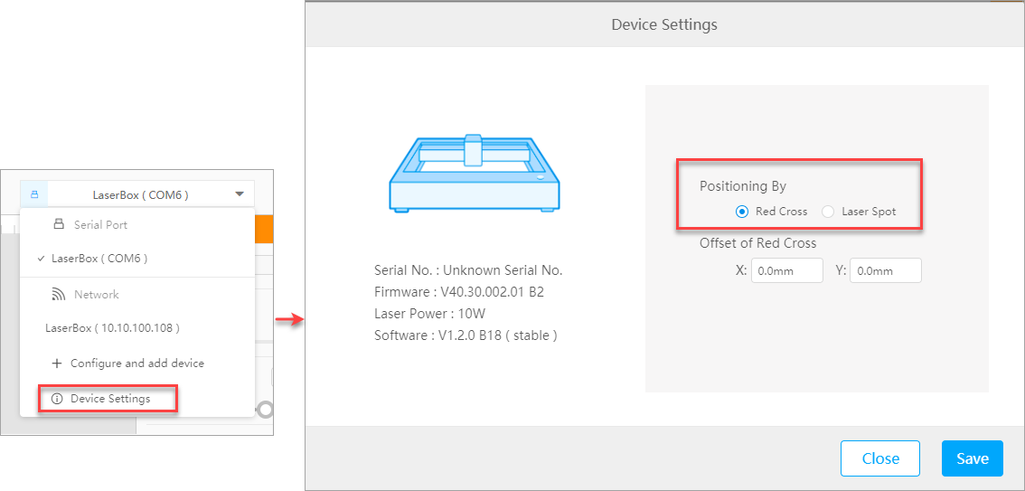
Red cross

- You may find the angle of the red cross not a right angle due to light refraction of the light shield.
- The center of the red cross may be 1 mm to 2 mm away from where the laser beam actually falls. When this happens, you can set the offset to perform calibration.
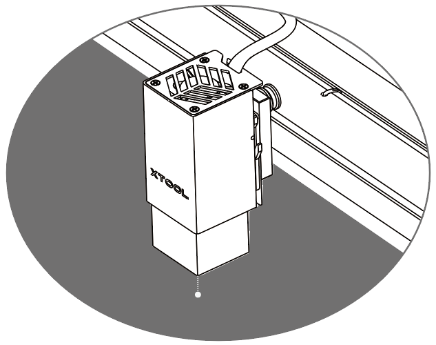
Laser spot
5. Start cutting or engraving
After finishing the drawing or editing of an object to be cut or engraved on the canvas, click the Start working icon in the upper-right corner to start cutting or engraving.
The Working window is displayed.
Select the processing type according to the material to be processed.
- Flat: processes flat materials, such as wooden boards, leather, and metal sheets
- Rotary: processes cylindrical or irregular materials
Note: To process cylindrical or irregular materials, you need to raise xTool D1 and connect it to a rotary attachment. For details, see "Connect RA2 to xTool D1."
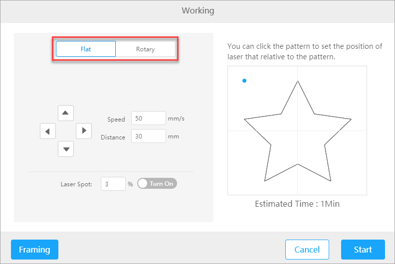
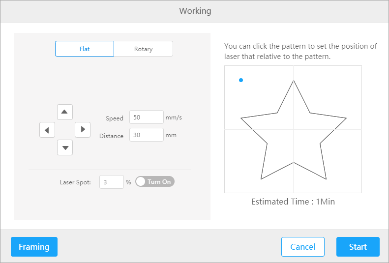
Flat processing
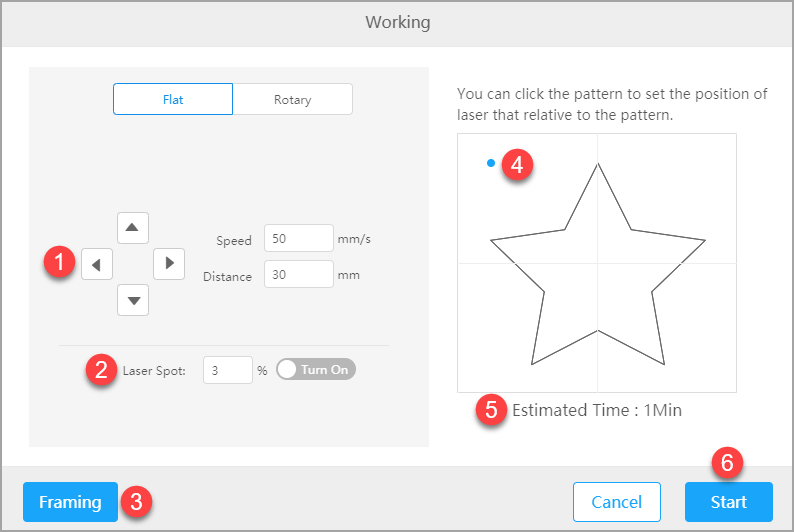
① Moves the laser module forward, backward, to the left, or to the right
Speed: sets the speed at which the laser module moves; setting range: 1–150 (mm/s)
Distance: sets the distance the laser module moves at each time; setting range: 1-300 (mm)
② Enable or disable the laser spot mode and set the power
③ Click to preview the movement of the laser module.
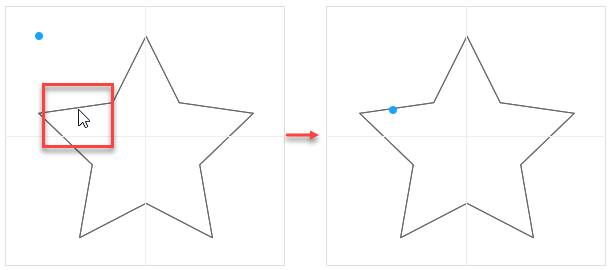
④ Click to set the start point of the processing on a design element.
⑤ View the estimated time required for completing the processing
⑥ Click to start processing
Rotary processing
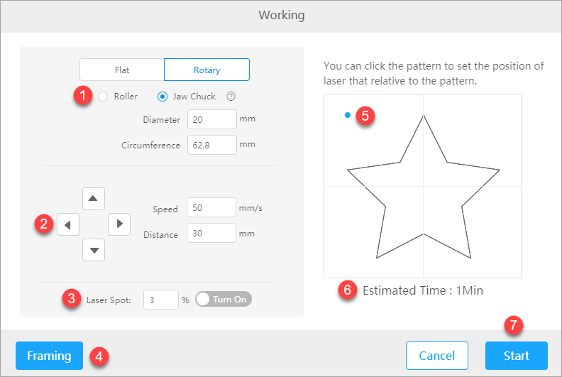
① Select a processing mode according to the parts of RA2 you are using.
- Rollers: Rollers are used.
- Jaw chuck components: The jaw chuck and parts working with it are used.
-
-
-
- Diameter: Enter the diameter of the material to be processed; setting range: 1.0–318.2
- Circumference: Enter the circumference of the material to be processed; setting range: 3–999
-
-
② Moves the laser module forward, backward, to the left, or to the right
Speed: sets the speed at which the laser module moves; setting range: 1–150 (mm/s)
Distance: sets the distance the laser module moves at each time; setting range: 1-300 (mm)
③ Enable or disable the laser spot mode and set the power
④ Click to preview the movement of the laser module.
⑤ Click to set the start point of the processing on a design element.
⑥ View the estimated time required for completing the processing
⑦ Click to start processing
After clicking Start, wait for the processing to complete.
Comments
Article is closed for comments.